
mk484
UN RECEPTEUR SIMPLE. Ce récepteur superhétérodyne à détection moyenneéquence fr à réaction a vu le jour suite à de bonnes lectures et d'intenses cogitations : Je voulais voir comment se comporterait dans les bandes actuelles un appareil simplifié et puis, n'ayant jamais utilisé de lampes Rimlock dans un nouveau montage en dépit.
Un mini récepteur FM simple à réaliser sur circuit impriméo
Mini-récepteur MRX-40 - réalisation complète (pdf) Modification d'une tête satellite. Modification d'une tête satellite pour la réception de la bande amateur 10 GHz.. Ce circuit radio AM démontrera comment une onde radio est reçue et détectée à l'aide d'une conception très simple fréquence radio syntonisée (TRF). Récepteur.
Schema electrique emetteur recepteur radio pdf · Schema electronique radio transistor radio
08/04/2014, 11h02 #1 werixhet Date d'inscription avril 2014 Messages 8 schéma récepteur radio am ------ Bonjour je recherche un schéma pour réaliser un projet pour l'école: un récepteur radio.

Émetteur et Récepteur CW 72 MHz
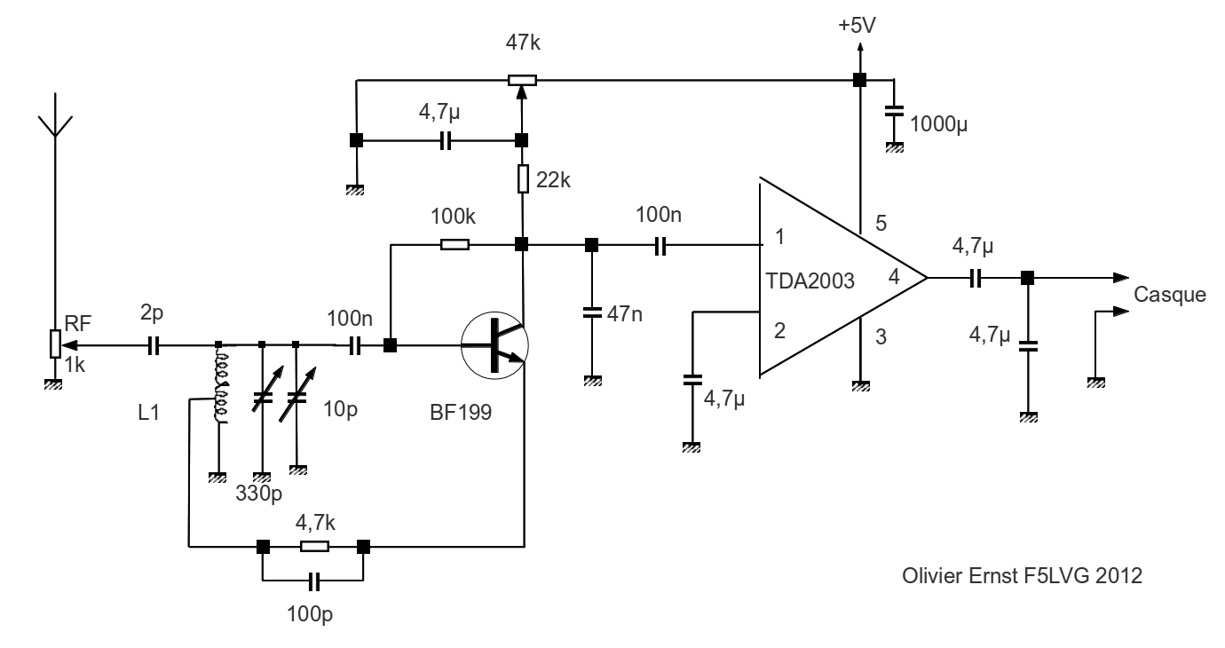
FM Receiver Circuit Schematic. The coil details are presented in the fm receiver circuit diagram. The radio receiver is adjusted on different stations with the help of C5. P1 potentiometer is adjusted untill the best reception is obtained. If we attach an audio amplifier and a speaker then this frequency modulated receiver can be made very.

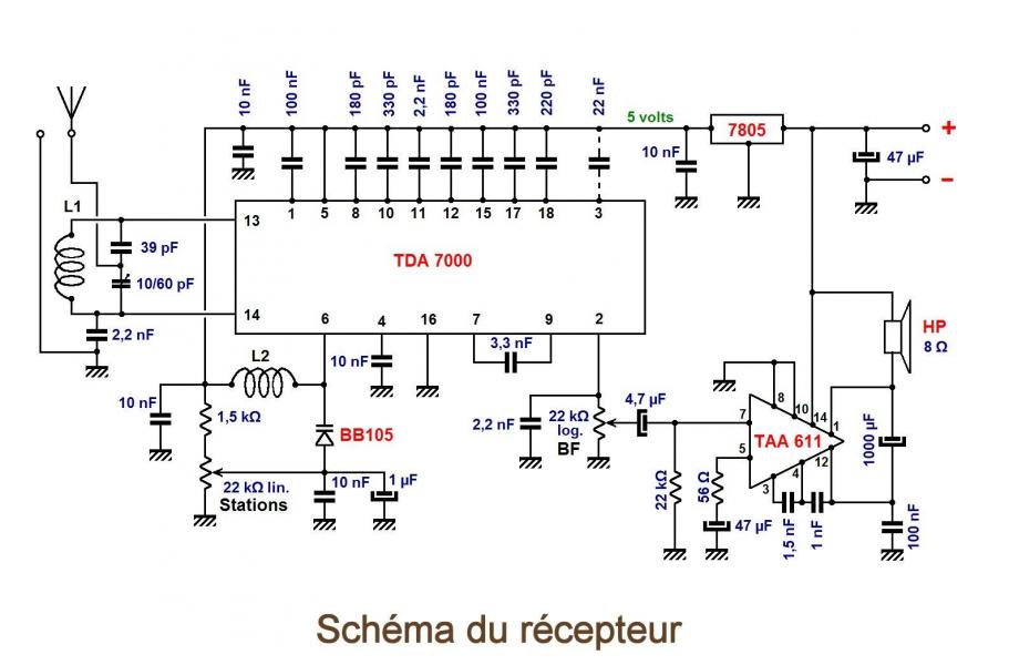
Récepteur VHF Nous vous avions proposé en fin d’année un article concernant la réalisation d
An FM radio receiver is an electronic configuration that takes in FM radio waves and converts them into an audible form. Basically, It takes the modulated FM signal as an input and outputs the original audio signal to an audio transducer such as a loudspeaker.

smog traversier Hibou schema electrique emetteur recepteur radio pdf Se sentir mal Anneau dur
1. Circuit antirésonant Les émetteurs «grandes ondes» ont des fréquences comprises entre 150 et 250 kHz. Il faut faire un circuit «anti-résonant» réglable dans cet intervalle. Nous avons choisi d'utiliser un condensateur de capacité constante, associé à une inductance variable.
schema Récepteur à réaction 34 & 5.518 MHz electro schematic
Dans cette vidéo, je présente comment effectuer un échange simple entre un émetteur et un récepteur de radio fréquence pour Arduino. Il s'agit simplement d'u.
The principle of operation of radio transmitter circuit with explanation Electronic Circuit
TA7642 IC. Additionally, this TA7642 is significant for low voltage portable Radios. It is accessible in the package of UTC7642 is TO-92. Thus, the featuring highlights of this IC have a low operating voltage, a very nominal input voltage (Vcc) which is around 1.3V, and a low Quiescent Current ICCO which is 0.2mA and requires a few other.
FM transmitter
Although the ubiquitous LM386 IC was designed to be used as an audio amplifier, it has a number of undocumented characteristics that can be exploited to create simple radio receiver circuits that deliver surprisingly high performance. These circuits can be used for receiving AM, CW, and SSB RF transmissions in the medium and shortwave bands.
schéma
R1 = 1K 1/4 watt 5% resistor. Earphone (magnetic) This is a fascinating small single transistor FM receiver that, unbelievably, can tune the full 88-108 MHz FM music band while still producing enough energy to power a typical set of magnetic earbuds. The tiny receiver is so small that it could be integrated into an empty cigarette pack.
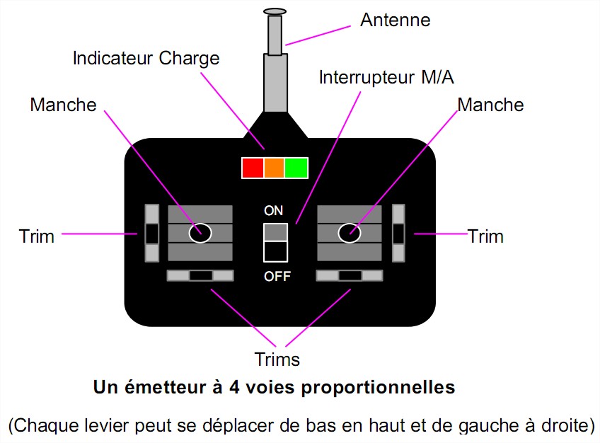
III . Le récepteur (à installer évidemment dans le modèle !)
SCHEMAS NRD525. JRC NRD-525 schemas CFL-205 CFH-36A CAE-182 CGA-131 CGA-132 CDC-353 CMH-632 CDE-418 CBO-232 interface Interface CBO-232 CIRCUIT CGA-118 schema CHE-85 schema Others / autres documents => notices.htm. SCHEMA, SCHEMATIC DIAGRAM, CIRCUIT, RECEPTEUR RECEIVER JRC NRD525.

Shéma récepteur radio Fichier PDF
Question de m'amuser un peu, je construis un récepteur FM super simple à partir de pièces de récupération. Et il fonctionne!Circuit de récepteur FM assemblé.
Récepteur « Reflex » Ecoute sur hautparleur PO, GO et bande « Chalutiers
We would like to show you a description here but the site won't allow us.
Monter un kit récepteur AM Club Scientifique et Radioamateur de RueilMalmaison (F6KFA)
Simple High Performance MW Receiver Circuit. An Improved version of the above Medium Wave radio can be studied in the following paragraphs. Once built it can be expected to work immediately without any hassles. The MW receiver works with four transistors. The first transistor is configured to work in the reflex mode.
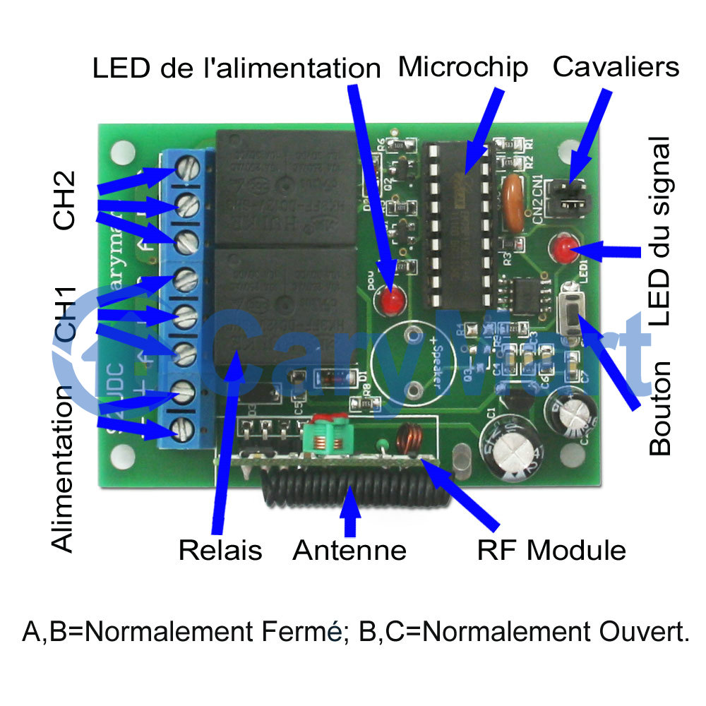
Kit Émetteur Récepteur Radio Avec Relais Fonction Mémoire 6V 9V 12V 24V 433Mhz 2 Voies 4 Fonctions
1 Réunissez les fournitures et les outils nécessaires. Vous êtes peut-être déjà en possession de certains de ces éléments, les autres seront achetés dans un magasin ou sur un site spécialisé en électronique. Il vous faudra : 1 résistance de 1 MΩ (10 6 Ω), 1 condensateur de 10 nF, 35 à 50 cm de fil électrique gainé rouge,

Les signaux sonores cours 5e (et 4e, 3e) Physiquechimie
• Affinez la fréquence sur votre poste radio pour trouver le silence radio. • Branchez le fil jack-jack sur l'entrée jack de la radio et sur votre source de son. • Mettez le volume de votre source de son au minimum et augmentez doucement le volume. Si tout s'est bien passé, vous devriez entendre votre son à la radio. Dépannage